Having some Carrera Go slot car racing sets at home I always regarded the included analog lap counters as kind of boring. I wanted to build a better lap counter with more functionality and which makes playing with a Carrera Go racing set feel more like an actual race. For me the included lap counters are missing a basic feature: Tracking the lap time.
The first idea was to use an ESP8266 and to make use of the WIFI capabilities (e.g. displaying lap times and speed on a website and having the possibliltity to make firmeware updates “over the air”). But after a second thought I came to the conclusion that it would also mean more complexitity and that the possiblity of OTA firmware updates would open the door to an never-ending project. I wanted kind of a finished product not an “always-beta” proof of concept. Something that just works and is easy to use, also for children.
- Features
- Parts needed
- 3D Printed Enclosure
- Digital Distance Sensors
- 4-Digit 7-Segment Displays
- Assembly
- Software
- Conclusion
Features
Here is the feature list of my advanced Carrera Go lap counter:
The lap counter features an on/off switch to, obviously, power it on or off. There are three buttons on the top, two white and one red. The buttons can be used to go through the “menu” and set, e.g. the number of laps for a race. In this case the white buttons are acting like + and - and can be used to increase or decrease the number of laps. The red button starts the actual race. Here is the lap counter in action: 
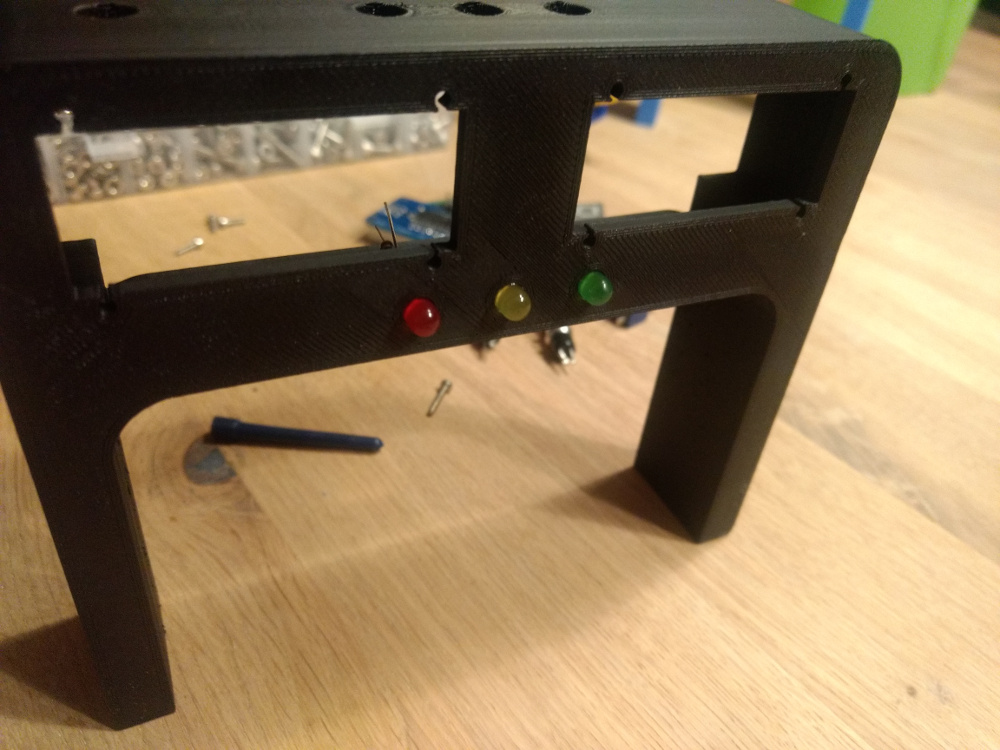
When a fixed number of laps is selected and the red button is pressed, the race begins with the starting lights. The starting lights are three LEDs in red, yellow and green. When the green LED is off the time tracking starts. Each time a car passes the sensor the lap is counted. 
When the first player has finished all laps off the current race the race result will be displayed and the race is over. With a press on the red button the next race can be started. 
When the current lap was the fasted lap of the actual race the lap counter displays the record. It is also possible to use the lap counter without a fixed number of laps. This is the “Free Race” mode. This mode works more or less like tracking the laps with the old analogue lap counters that came with the Carrera Go sets but with additional time tracking. 
Parts needed
Schematic

The lap counter uses an “Arduino Micro” microcontroller board. The main reason for choosing this board was the small form factor (48mm x 18mm) and it’s 20 digital input and output pins which makes it possible to connect a lot of things to it. Anyway, in the end, I only needed 10 pins. The Micro also supports I2C and interrupts, which I also needed.
Later I found out that the “PlatformIO IDE”, which I use to program microcontroller boards, does not work well with the Arduino Micro. Basically, it was not possible for me to upload code to the board without an error, not even once. I guess the problems are connected to the Micro’s virtual serial port and the way the board detects an upload. It was a matter of luck if an upload succeded and it always took me multiple tries. It was tedious.
Apart from the Arduino Micro the main parts where the Displays and the Sensors.
BOM
- 1x Arduino Micro
- 2x Sharp GP2Y0D805Z0F Digital Distance Sensor 5cm
- 1x Adafruit 0.56” 4-Digit 7-Segment Display with I2C Backpack - Green
- 1x Adafruit 0.56” 4-Digit 7-Segment Display with I2C Backpack - Yellow
- 3x Momentary Mini Push Buttons
- 1x Mini Toggle Switch
- LEDs, Resistors, Wire, Screws, …
- 1x 3D printed enclosure
3D Printed Enclosure
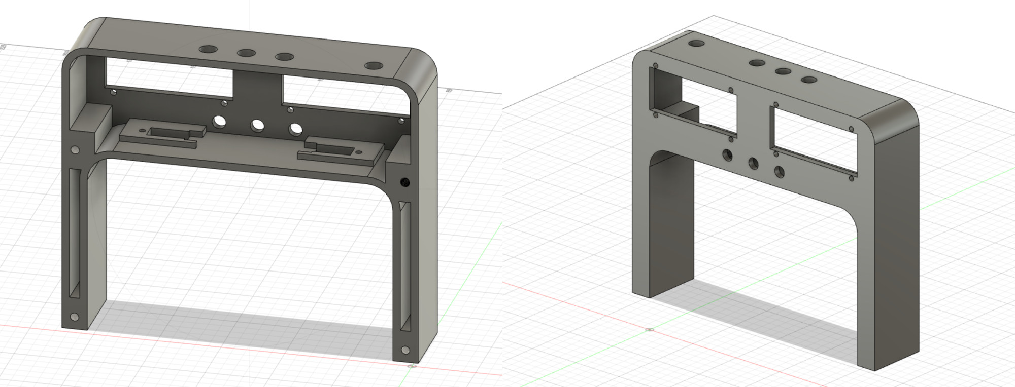
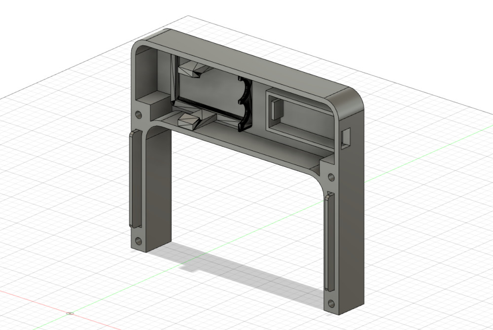
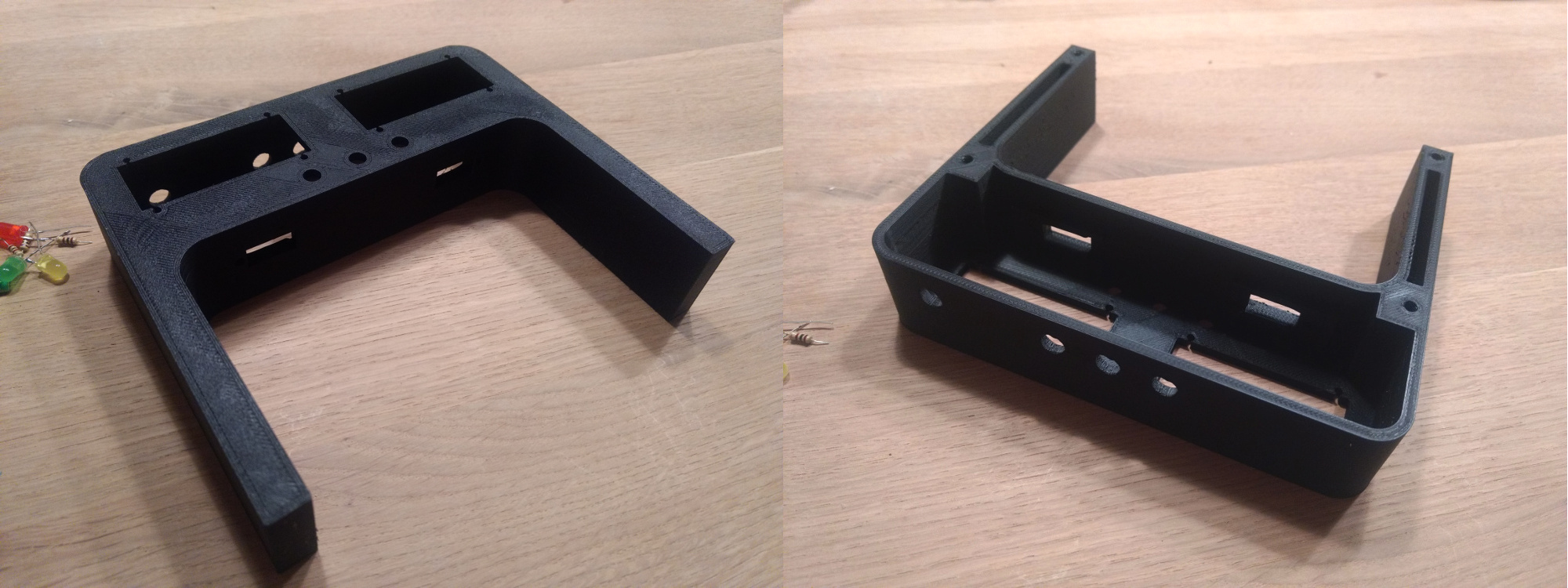
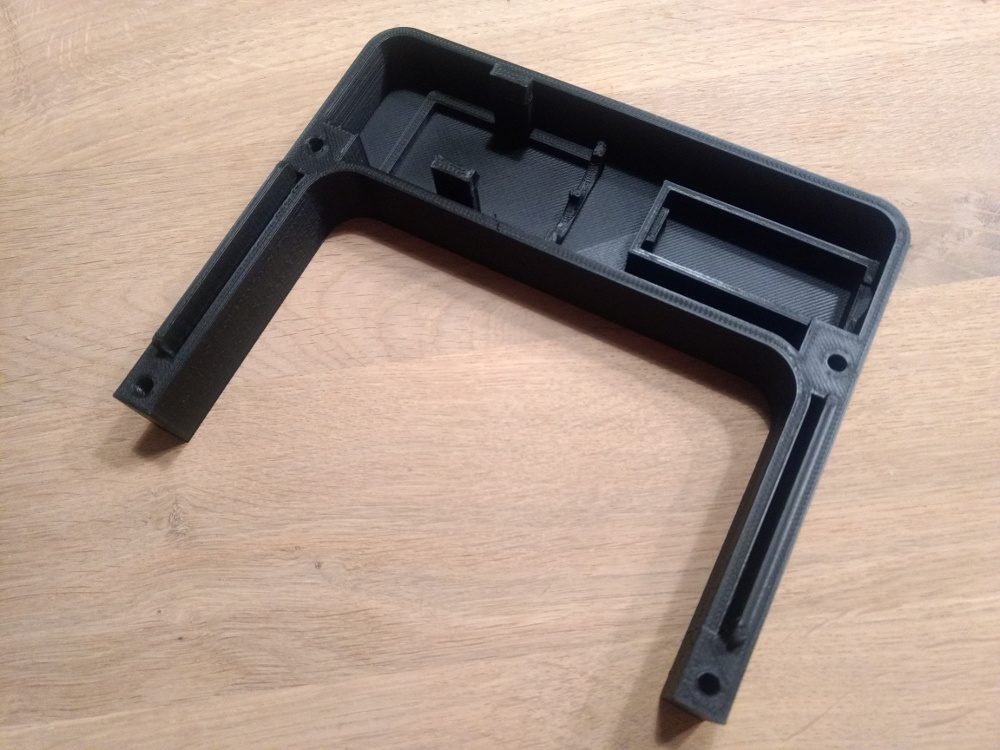 I designed an enclosure with Fusion360 and printed it with my 3d printer.
Digital Distance Sensors
The Sharp GP2Y0D805Z0F Digital Distance Sensors are very fast and accurate. They are placed in the enclosure above the track facing downwards. The data pins of the sensors are connected to the Micro’s interrupt pins 0 and 1. In the firmware he code defines two interrupt handlers via attachInterrupt and it looks more ore less like this:
const byte sensorPinPlayerA = 0;
...
class Player {
  public:
    volatile unsigned int ticks = 0;
}
...
void tickPlayerA() {
  playerA->ticks++;
}
...
attachInterrupt(digitalPinToInterrupt(sensorPinPlayerA), tickPlayerA, CHANGE);
...
4-Digit 7-Segment Displays
The Adafruit 0.56” 4-Digit 7-Segment displays are connected via I2C on the Micro’s I2C pins 2 (SDA) and 3 (SCL).
Adafruit has some documentation on how to get started and an Arduino library to control the displays. The library makes it easy to display numbers but also allows via 8 bit bitmasks to set individual segments to turn on or off. This is really useful for creating your own characters. This is how it looks in the firmware:
#include <Wire.h>
#include <SPI.h>
#include <Adafruit_GFX.h>
#include "Adafruit_LEDBackpack.h"
...

#define DISPLAY_A_ADDRESS 0x70
...
Adafruit_7segment display = Adafruit_7segment();
...
display.begin(DISPLAY_A_ADDRESS);
...
display.blinkRate(3);
Assembly
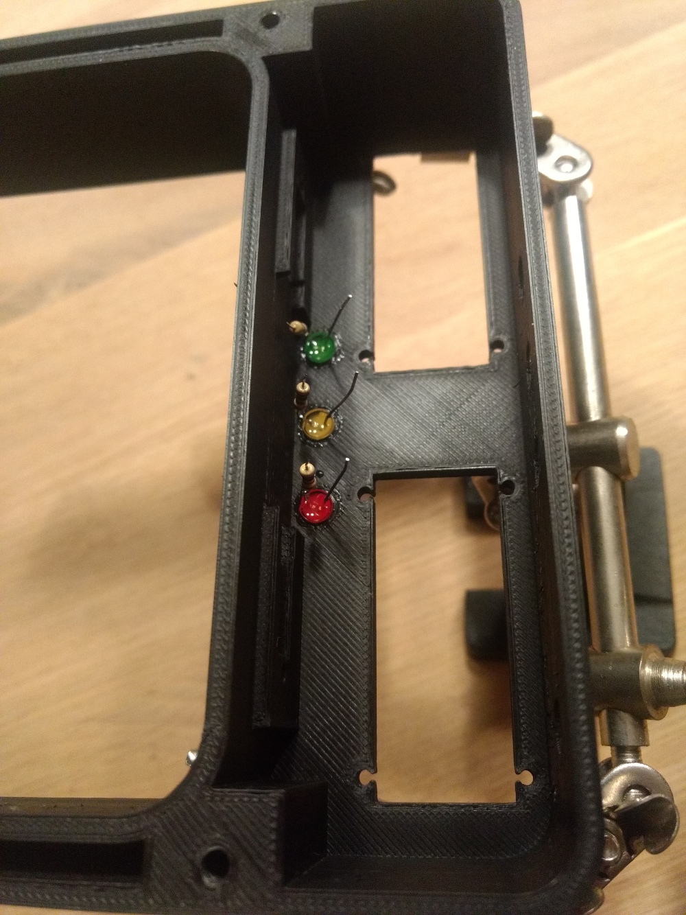
The first thing I did was to install the LEDs for the racing lights in the enclosure. I cutted the shorter leg of the LEDs even shorter and soldered an resistor to each. Then I fixed the LEDs in the enclosure with adhesive and bended the long legs (the ones without the resistor) together, so that I could solder a wire to all three of them. Finally I soldered the wires onto the Arduino Micro (pins: 10, 11, 12). Here are some pictures of the process: 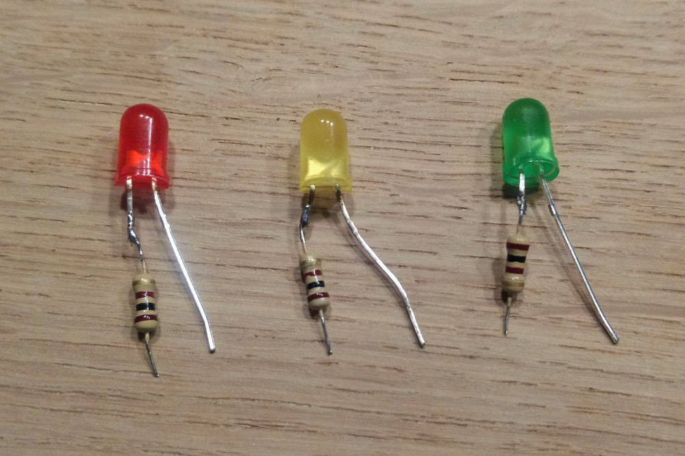
After that, I installed the displays, sensors, buttons and the power switch in the front part of the housing and the battery and the Arduino Micro in the back part. 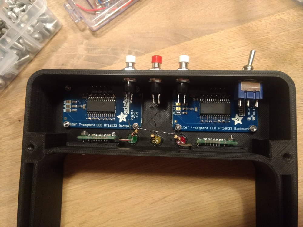
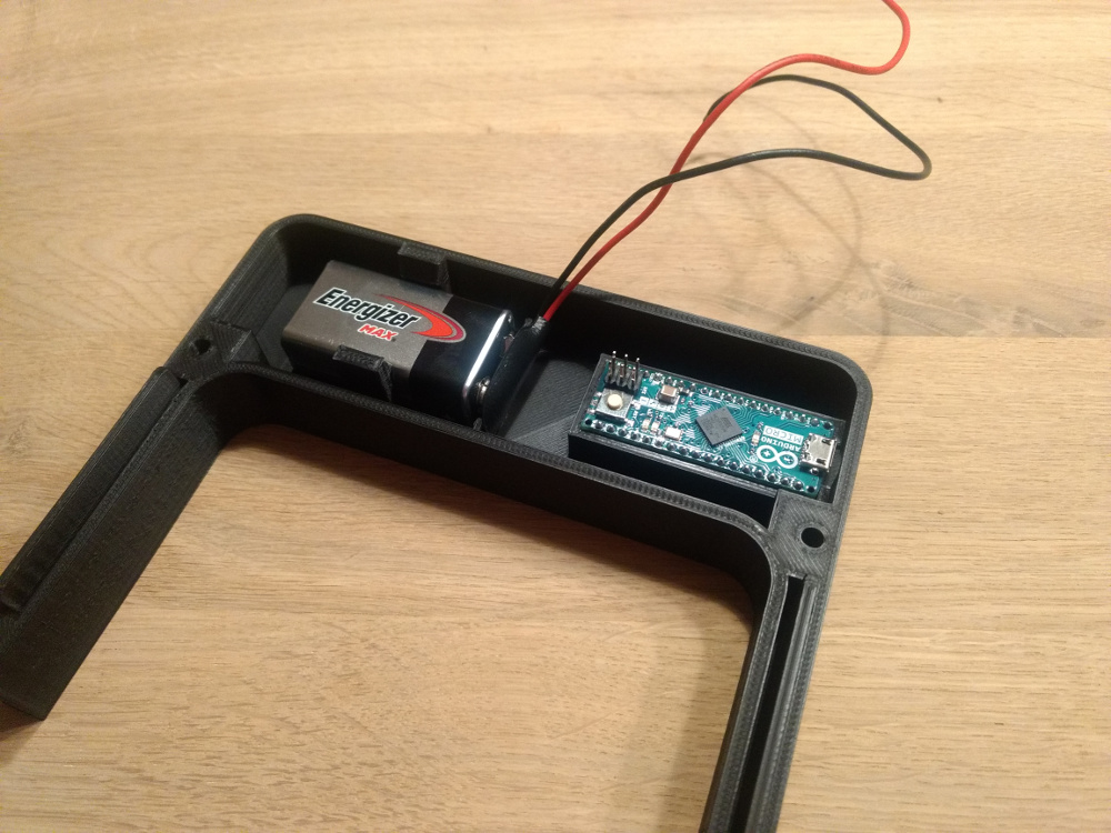
I soldered the power switch with wires to the battery and the Micro’s Vin and Ground Pins. 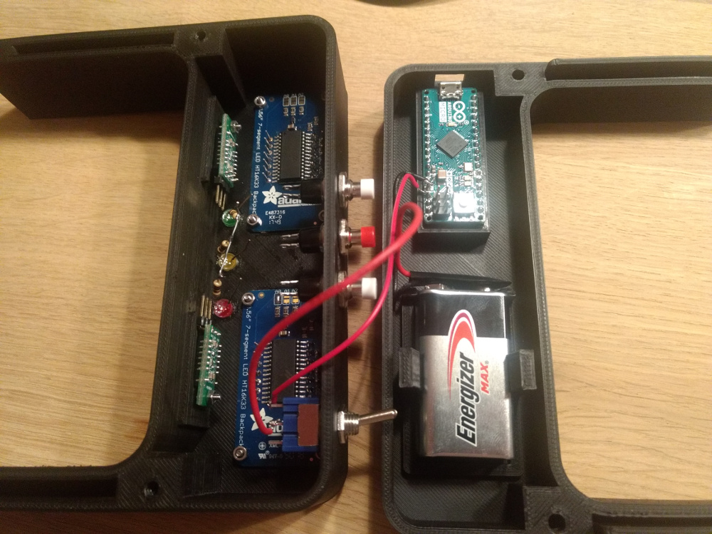
Then it really started to get complicated. I soldered the sensors and the displays to the Micro using two additional boards for all the + and - wires. I realized then, that perhaps this huge amount of cable won’t fit into the enclosure. 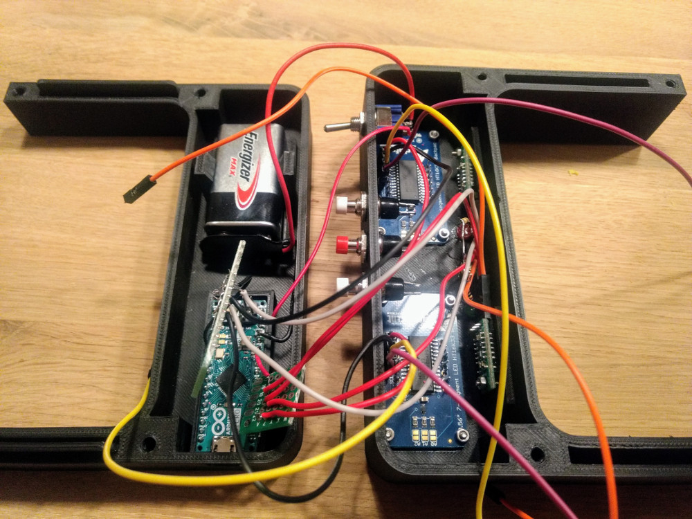
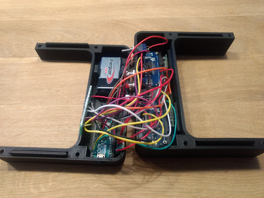
That’s why I added hot glue to the soldered connections to protect them from the pulling force that occured when I finally tried to close the enclosure. 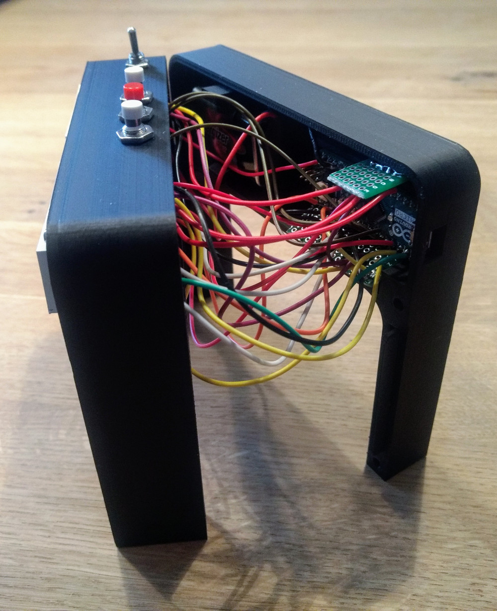
But somehow, with a lot of patience, I managed to stuff everything into the housing. 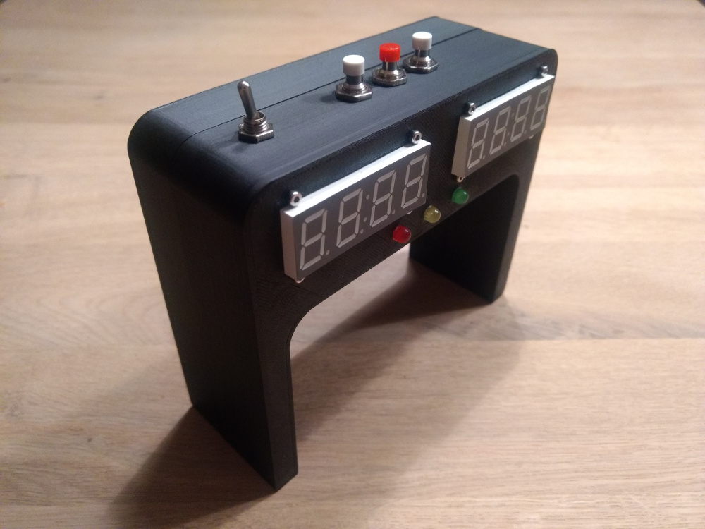
Software
I will problaly never publish the code because it is a mess and I’d have to invest a lot of time to clean it up.
Conclusion
Building the lap counter was a lot of fun and I learned a lot about designing an enclosure for electronics. It is not the prettiest one but it is a functional design and it works for me.
WRITTEN BY

Sebastian Glahn is a Senior Software Engineer living in Cologne. He writes about Software Development, 3D-Printing, Robots and other stuff. He is also a maintainer of several open source projects.